I understand Dan's philosophy. I thought along similar lines, figuring that I should start from the base that the sim will sit on and build up. Hence my infatuation with j-rails for so long.... (I will get to writing this bit one day, maybe once I've built the prototypes). What Dan and I agree on though, you've got to keep flying to keep your interest going.
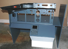
And here's where my foolish words come in. Back on Christmas day no less, I said I would "fit a 19 inch Acer screen" and "rig up some of the wiring and fly the sucker". Fat chance. The screen wouldn't fit in the MIP without a lot of modification to my beautiful (and expensive) Engravity desk top unit. Only option was to take the screen apart and heavily modify it.
Ok, probably now a good time to make some disclaimers. In this posting you will see me take apart an electrical appliance and rebuild it. I have a pretty good idea of what I'm doing but I'm no expert. If you follow along with my steps, you do so at your own risk. If you don't know what you're doing with 120 or 240 volt electrical supplies, I strongly suggest you get some help from an expert or don't follow what I'm about to share.
While we're about it, if you are a Boeing 737 engineer and hope to pick up some tips about how to build or repair a cockpit from this blog, you are delusional and need medical help. This is a representation of the real thing, not the real thing...
Ok, hope I'm covered from any potential litigation - you never can tell the crazies that read this stuff..
So, let's start with an Acer 19 inch wide screen monitor:

You know, I read a funny posting this week on someone else's blog about how crappy most blogger's photos are. He's right - mine are no better. They're here to add visuals to the description, I don't think you'll be printing them off and hanging them on your wall..
Anyway, first thing to take off is the stand:

With that out the way, you can force the bezel off the back and get into the innards. At this point you have voided your warranty (maybe I should have said that first, hmmm.....). And here's where I ran into a problem. Even with the back off, the unit was too big to fit in the MIP and at the same time give me reasonable wire runs for power and the VGA cable. Nothing else for it - we'll need to rebuild the unit so that it will fit.

Next we need to unhook the printed circuit boards from each other and from the LCD panel. First part easy - the data goes through this ribbon cable:

Second part - trickier. What looks like the power cables for the backlighting - be patient, ensure you don't snag or cut through the thin wires on the sharp chassis:

To get at the connectors (and I've been thinking for at least a couple of nights I'd need to cut and splice these wires, because on first inspection the looked like they were soldered in place) I had to disconnect and lift up the circuit board:

If you look closely you'll see that I marked the circuit board with a Sharpie so that I know which wire goes to which connect (WR - white/red, BG - blue/grey).
Now completely disconnected from the old frame, I need to fabricate a new backing for the LCD that will allow a fit and better positioning for all of the external connections. In short I had to move the whole thing up to the top of the screen. How to do it?
I have a workshop that is set up for woodworking, metal working? Not so much. At this point I must say I could hear the voice of my old shop teacher from high school - Mr. Clack (no kidding - that was his name. Nice guy. Made the mistake of trying to teach me aeronautical engineering but that's a different story). He had this way of talking - a loud yet nasal whine that would always put the fear of Christ into us kids. A favorite saying was: "Son! What do you think you're DOING?". This is what I was hearing all day today...
Why? Because I decided to make the new frame out of a nice piece of oak I had lying around in the shop. Hey it's non conductive, can be easily cut and molded and will be easy to fit a mounting bracket to once I get it into the MIP. It just looks.... a bit funny that's all.
So here it is - isn't she a beauty?

I tried to fit everything into the one shot so you can see what I did. First off, I recycled the cut out from the bottom of the MIP (see last posting for details) and made 2 brackets that fit the screw holes on the LCD panel. The yet to be attached bracket is sitting on the ribbon cable, accomponied by a screw, prior to deployment. I cut slots in the brackets for the screw that goes into the end grain of the oak. This way there's some adjustment fore and aft if needed. You'll also notice that I cut out a rabbet at the top. It's 1/4 of an inch to accommodate the electronics underneath. I also cut a slot for the ribbon cable and a couple of holes on the other end for the backlighting power cables.
Here it is with the printed circuit boards mounted:

So now, I can screw some kind of mounting bracket (yet to be devised - stay tuned!) to get the thing finally in the MIP. I'll also screen the components with a metal cover to prevent shorts, electric shocks and interference. For now though I'm happy with the fit - the power and video connections are high enough on the screen that they can be connected without any foul ups on the MIP. But does the thing still work?
It was with some trepidation that I plugged it in and fired it up. Not so much that I might have damaged the thing beyond repair (monitors are so cheap these days - how do they do it?), more a concern that it may not work after all of this time and effort.
I had the wife throw the power switch on my Frankenstein's monster (hey, good to involve partners in your hobbies) and as you can below:
IT"S ALIVE!! IT'S ALIVE HA HA HA HA!

Cool looking website - must check that out sometime...
Next up, I actually fly the sim (no kidding, serious this time).


No comments:
Post a Comment