Saturday, January 30, 2010

Wiring, wiring, wiring

Expect not one but 2 updates this weekend!

A rainy, miserable week in San Francisco. Plus the wife's out of town on a 2 week business trip! Yahay! More anorak time.

This week focused on getting the EICAS screen ready. What you need is a 10" LCD display. Not easily come by in this day and age of huge TV screens but you can find them. I got this one on eBay for $40 - it's a miracle! (sorry, couldn't resist):


Now the thing with this monitor is that it has an external power supply, so less concern about killing yourself when you take the back off and plug the thing in. Plus I won't need to make any special shielding for the power supply, since it already is.

So here it is with the back off and the warranty (what warranty?) voided:

Now for some reason Blogger has rotated this photo and I can't figure out how to change it. Sorry. Also since I walked you through a screen redo in a previous post, I'm not going to dwell on it a second time. Suffice to say that even with the plastic case off, the chassis is too big to fit in the slot on the center panel. So out with the snips to trim it down and a redesign of the brackets that hold the LCD panel to the chassis. I also trimmed down the plastic case to give the innards some protection, which I skillfully attached to the chassis with.... duct tape. Draft excluder on the screen front to protect the Plexiglas screen on the center panel, and voila:

Bride of Frankenstein? Could be. You'll notice I left the tabs on the bottom, this is so I can affix it to a mount. And does it still work? Yes:


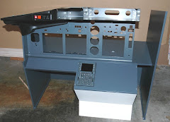
"It's a miracle!" I hear you say! (ok, enough with the miracle jokes). Now it's small enough to fit in the center panel and still have clearance for the landing gear lever (which doesn't line up with the pre-drilled holes in the center panel - nice work Engravity!) and the standby gauges. I'll get it mounted this weekend.

Other project this week was to come up with a working dimmer circuit for the panel backlighting and for an LED strip I'll mount under the glare shield. It isn't as simple as just putting a potentiometer in between the LEDs and the power supply (trust me, I tried). You need to build a circuit that switches the power to the LEDs on and off so fast, you can't see it. You control the duration of how long it's off by using a timer chip, a transistor, a couple of diodes and a potentiometer. Here's one I found from Bill Marsden (you'll need to register to see this but I highly recommend the site anyway) via the esteemed Sgt. Wookie.

I've been messing around with the design for a couple of weeks and couldn't get it working. I finally broke down and purchased a couple of prebuilt units from these guys. Wouldn't you know, since the shipping time (from Hong Kong) is so long I thought what the heck, let's give Bill Marsden's circuit another try. I realized I had the capacitor rating wrong, popped in the correct ones and the things works like a charm!:
 

Sorry, hard to get it all in focus - that's the potentiometer in the foreground and the LED strip at 50% brightness over my test board. Next step is to fit all of the components on the circuit board the chip is already mounted to.

While at it, I thought it was time to tackle the panel backlighting kit from Engravity. They really don't give you much to solder onto. At first I was worried about melting the plastic backing with the soldering iron, happy to say it has a higher melting point that solder so it was ok. I had to use some stripped down cat 5 wire to get it in there but here's the result:

You really need to ensure that there is no solder between the contacts otherwise (of course) you'll have a dead short. You'll notice I also put some heat shrink tubing on the leads to give it some projection from the panel. I must say though that when you light these guys up, they look magnificent! I'll save the photo for when I have them all mounted to the panels.

Progress on the software side. You'll recall that the autopilot wasn't working properly last week. I installed the latest release of Project Magenta and made sure the Netdir setting was correct. Now working fine. I still have the problem of the flight plan not being displayed in the ND, rather it shows the direct route to the destination airport. So I still need to work on this.

What else? Moved the weight bench and rowing machine out of the room, so my plan for the weekend is to re-arrange the guest bedroom and maybe even get the base built to mount everything on. More later - the sun is out and the dog needs walking... 

Sunday, January 24, 2010

It flys (just like the time you blow on it....)

I left my last post by saying I was really going to fly the sim this week and I can report, yes I met the goal. 2 short hops, one from SFO to LAX, the other from SFO to LAS. How was it? Magical to have a full size PFD and ND. Having the CDU in a fixed position for the first time was a revelation also. Did it all go smoothly? Er, not quite. More on that in a bit.

First a recap of construction for the week. I decided to reuse the metal shielding from the screen instead of fabricating something myself. All I needed to do was take the snips to the thing and cut it down to size. A couple of holes drilled for the screws and a quick mount to the oak backing:


I also hacked off part of the bezel to provide some protection to the circuit board and buttons for the power switch, menu button and so on. Pretty neat eh? Now with the circuit boards mounted high on the screen, there's plenty of room for the power and video cables underneath. Also, by reusing the shielding I was able to utilize the mounting holes and then hack down the original mounting bracket.

In my last post I was slagging off Engravity for the placement of the uprights that connect the captains console to the center one. Turns out that with the thick aluminum bezel in place on the front, there is plenty of clearance for the LCD without any visual obstruction of the screen edges. So here is "Frankenstein" mounted in place:


You'll notice I used some extra thick self adhesive draft excluder to prevent light from other sources leaking into the displays. Have yet to attach the mounting bracket to the MIP but it seems to be holding it in place just fine as it is.

Dan's handles arrived on Saturday! Wife comes in the house from the mailbox all smiles - "your plastic samples for your toy are here!". What? Turns out that's what Dan wrote on the customs label on the envelope (gee thanks Dan!). So here they are:

Alright then! Will move up the fabrication of the TQ to get these puppies put to work.

And now back to the lead in part of the story. Took off from SFO no problem. On climb out switched to the auto pilot, hit the LVL CHG button and watched the nose rise up. What didn't work though was LNAV or HDG - no effect at all. I had to take control back and steer it on course manually. The MCP is definitely talking to the computer running FSX, since the speed and altitude settings have an effect on the flight.

Also noticed that even though the route is in the CDU, it isn't shown correctly in the ND (it just shows direct from SFO to LAS):


So we'll need to get to the bottom of this - not sure if the problems are related or not. Nevertheless, the plane intercepted the localizer on approach and started to head down on the glide slope. Only problem, it was not aligned on the runway - took manual control back and landed without incident (hey not bad considering I haven't flown in months).

Check out the current state photo on the right hand panel. It's another blurry photo (where is my tripod?) but it shows how great the CP flight MCP and EFIS look when light up. You'll notice a projector sitting on top of the glareshield. I borrowed it from work for the weekend. Due to the short video cabble, I couldn't get any distance on the thing from the computer. So no big screen experience this week. A keen eye will also notice a drum crown instead of a captains chair.... not enough room for it - see next paragraph. On the floor where the avionics console should be is my current stack of GoFlight radios.

What else? Well despite taking accurate measurements of the guest bedroom and figuring that the available space would be big enough for the sim, what I failed to take into account was that I'd need room to work behind the thing during construction. So I've talked the wife into moving the weight bench and the rowing machine into the formal living room we never use (in fact we call it the yoga room. Something neither one of us practices...). Cool - more room for the sim!

Next up - fix the problems with Project Magenta and break down yet another LCD monitor for the EICAS...

Tuesday, January 19, 2010

A mini mid week update

Last night did a dry fit of the Frankenstein LCD in the MIP. Needed to tweak things a little but take a look at the result:

Sorry about the camera shake and the color balance. What we're really interested in is whether we can see the PFD and ND - the results speak for themselves.

I'm still not 100% happy with the angle of the screen but I'll continue to fine tune it. Why the problem? Well to get the screen in the right spot to not have a gap on the right hand side of the ND, I'm butting up against one of the uprights on the Engravity MIP (hello fellas - please take note):


So maybe I'll grind down part of the Engravity upright or figure something else out. It's really very close though.

While on the topic of Engravity's workmanship, I did need to drill a hole in the center panel to accommodate the MFD buttons. Not sure if this was a one off on my unit or whether this is a problem in general. Here's what the finished result looks like:


See where the ENG and SYS switches are? There was no hole in the MIP for it (and the switches were supplied by Engravity too). I screwed the plate on top to use as a template, marked where the hole needed to be then set to with the drill and grinder. Not the squarest of efforts but then again the plate will cover the mess. More important is that the buttons don't get fouled up on the metal work:


You know you pay a lot for this stuff...

Just got an email from Dan - the throttle handles are in the mail Yahoo!

Sunday, January 17, 2010

My foolish words

There must come a point for every blogger, when you get that first inclination that someone is actually reading this thing! I had that moment this week. Someone had left a comment. Must admit it took me a while to realize it was there, nevertheless I was happy that someone was actually moved enough to check in. That person is Dan. He is a builder of throttle handles. His approach to building a sim is that it all starts with the throttle quadrant and the things you touch (the handles themselves) should be as realistic as possible. You can read more about it here. Needless to say I ordered a set right away. I'll write up more about the handles in a future post.

I understand Dan's philosophy. I thought along similar lines, figuring that I should start from the base that the sim will sit on and build up. Hence my infatuation with j-rails for so long.... (I will get to writing this bit one day, maybe once I've built the prototypes). What Dan and I agree on though, you've got to keep flying to keep your interest going.

And here's where my foolish words come in. Back on Christmas day no less, I said I would "fit a 19 inch Acer screen" and "rig up some of the wiring and fly the sucker". Fat chance. The screen wouldn't fit in the MIP without a lot of modification to my beautiful (and expensive) Engravity desk top unit. Only option was to take the screen apart and heavily modify it.

Ok, probably now a good time to make some disclaimers. In this posting you will see me take apart an electrical appliance and rebuild it. I have a pretty good idea of what I'm doing but I'm no expert. If you follow along with my steps, you do so at your own risk. If you don't know what you're doing with 120 or 240 volt electrical supplies, I strongly suggest you get some help from an expert or don't follow what I'm about to share.

While we're about it, if you are a Boeing 737 engineer and hope to pick up some tips about how to build or repair a cockpit from this blog, you are delusional and need medical help. This is a representation of the real thing, not the real thing...

Ok, hope I'm covered from any potential litigation - you never can tell the crazies that read this stuff..

So, let's start with an Acer 19 inch wide screen monitor:


You know, I read a funny posting this week on someone else's blog about how crappy most blogger's photos are. He's right - mine are no better. They're here to add visuals to the description, I don't think you'll be printing them off and hanging them on your wall..

Anyway, first thing to take off is the stand:


With that out the way, you can force the bezel off the back and get into the innards. At this point you have voided your warranty (maybe I should have said that first, hmmm.....). And here's where I ran into a problem. Even with the back off, the unit was too big to fit in the MIP and at the same time give me reasonable wire runs for power and the VGA cable. Nothing else for it - we'll need to rebuild the unit so that it will fit.


Next we need to unhook the printed circuit boards from each other and from the LCD panel. First part easy - the data goes through this ribbon cable:


Second part - trickier. What looks like the power cables for the backlighting - be patient, ensure you don't snag or cut through the thin wires on the sharp chassis:


To get at the connectors (and I've been thinking for at least a couple of nights I'd need to cut and splice these wires, because on first inspection the looked like they were soldered in place) I had to disconnect and lift up the circuit board:


If you look closely you'll see that I marked the circuit board with a Sharpie so that I know which wire goes to which connect (WR - white/red, BG - blue/grey).

Now completely disconnected from the old frame, I need to fabricate a new backing for the LCD that will allow a fit and better positioning for all of the external connections. In short I had to move the whole thing up to the top of the screen. How to do it?

I have a workshop that is set up for woodworking, metal working? Not so much. At this point I must say I could hear the voice of my old shop teacher from high school - Mr. Clack (no kidding - that was his name. Nice guy. Made the mistake of trying to teach me aeronautical engineering but that's a different story). He had this way of talking - a loud yet nasal whine that would always put the fear of Christ into us kids. A favorite saying was: "Son! What do you think you're DOING?". This is what I was hearing all day today...

Why? Because I decided to make the new frame out of a nice piece of oak I had lying around in the shop. Hey it's non conductive, can be easily cut and molded and will be easy to fit a mounting bracket to once I get it into the MIP. It just looks.... a bit funny that's all.

So here it is - isn't she a beauty?


I tried to fit everything into the one shot so you can see what I did. First off, I recycled the cut out from the bottom of the MIP (see last posting for details) and made 2 brackets that fit the screw holes on the LCD panel. The yet to be attached bracket is sitting on the ribbon cable, accomponied by a screw, prior to deployment. I cut slots in the brackets for the screw that goes into the end grain of the oak. This way there's some adjustment fore and aft if needed. You'll also notice that I cut out a rabbet at the top. It's 1/4 of an inch to accommodate the electronics underneath. I also cut a slot for the ribbon cable and a couple of holes on the other end for the backlighting power cables.

Here it is with the printed circuit boards mounted:


So now, I can screw some kind of mounting bracket (yet to be devised - stay tuned!) to get the thing finally in the MIP. I'll also screen the components with a metal cover to prevent shorts, electric shocks and interference. For now though I'm happy with the fit - the power and video connections are high enough on the screen that they can be connected without any foul ups on the MIP. But does the thing still work?

It was with some trepidation that I plugged it in and fired it up. Not so much that I might have damaged the thing beyond repair (monitors are so cheap these days - how do they do it?), more a concern that it may not work after all of this time and effort.

I had the wife throw the power switch on my Frankenstein's monster (hey, good to involve partners in your hobbies) and as you can below:
IT"S ALIVE!! IT'S ALIVE HA HA HA HA!


Cool looking website - must check that out sometime...

Next up, I actually fly the sim (no kidding, serious this time).

Tuesday, January 12, 2010

Kickback and relax

Got to spend some time in the workshop this weekend. Decided to add a panel for the light dimmers now, so I can get the MIP finish coat on in one go (if you check out the Current State picture on the right, you'll see the color matching job Home Depot did - not bad):


Also shown here is the Engravity CDU sitting in the forward panel. More on this later.

My intent is that this blog be somewhat instructional and educational, so to that end I feel it only fair to share my mistakes. Can you guess what caused this:


It's a piece of maple embedded in the drywall and is a result of kickback. Kickback is something that can happen when using power tools, in this case my table saw. I've used the saw for years and it's been about as long since I encountered the problem. What went wrong? Stupidity on my behalf. I needed a piece of blocking to go behind the light dimmer panel. Rather than cut a piece off using the chop saw, I found a piece of scrap lying around that had a beveled edge. "No problem, I'll just whip that through the table saw to cut it off". Since the piece was only about an inch and a half wide, I didn't have much of a grip on it, to hold it fast to the fence. It got loose from me, caught the top the blade and shot through the drywall. All that saved my pretty face (and the wife may argue it isn't that pretty to begin with) was my technique of always keeping my body to the side of the blade, instead of being directly behind it. Even then, I got lucky.

Moral of the story - if you're going to use power tools, read the manuals, use safety features, always be on your guard, adopt good practices, don't get complacent. A bit like real flying I suppose.

Still don't have the primary flight display screen in, so let's turn our attention to it. Now I know that the Acer 19" monitor I have is too high for the Engravity frame. A cut away panel is provided so you can drop the bottom of the screen through the MIP console:


You can just make out the little bits of metal you need to cut through. I'm using a small cut off tool to do the job. If you use snips there's a chance you will bend the thin aluminum.
Here it is with the cut away panel removed and the metal "sticks" ground down


With the frame screwed into the top and the forward panel bolted to the MIP console, it's an easy job to mark where we need to cut through. I need about 1.5 inches clear of the bottom - we'll see this in a later post.

What else is going on? I purchased another set of CH Products yoke and pedals on eBay (Bernd, are you reading this?), to tear down and incorporate into the sim. Will use them as a basis for a more realistic look and feel set, similar to Ian's efforts seen here. I got the gear from Bret in DC. He used them while practicing for a check ride in a real airplane. Nice chap even threw in a book on using flight simulators as a training aid.

All for now, other than I ordered a set of analog guages from Flight Illusions today (ouch!). Hopefully the lead time won't be 8 to 9 weeks....

Next up, I pull apart a working Acer 19" monitor to fit into the MIP.

Sunday, January 3, 2010

A message to you Rudy

A brief post to thank "my man in Belgium", Rudy. He has posted the plans I'm loosely following and without his head start, the job would be taking much longer. He continues to innovate and update us on progress via his excellent web site. So if you have an urge to try something similar, you really should check this out. Rudy continues to be an inspiration and makes me strive for the next level of realism. Vous continuez à être une inspiration - merci beaucoup.

Closing my last post, I mentioned that I hoped to get the paint on the stand and forward panel, drop the screens in the MIP and fly.... Well it didn't quite progress that far but I did finish painting the dining room. We then took off of the new year long weekend and so the final coat of Boeing grey awaits my return.

One tip on painting fiberboard - you need a good primer. The one I used is a shellac based product, B-I-N by Zinsser.

The problem with fiberboard is that it soaks up the paint quickly, so what you want is a fast drying primer. This does it. I used a small foam roller and brush for the edges. After the second coat I was a bit alarmed to feel how rough the surface was. A quick, light wipe down with 220 grit abrasive and the results are silky smooth, even the bare edges of the panels.

Exciting stuff, I know. Tis the stuff of anoraks though...

Also been working on a dimmer circuit for the LEDs that will go in the panels. More on this in a future post.