Dear fellow anoraks. Work and travel demands I be on the road for the next 10 days, so don't expect an update until the first week of April. May be just as well, since there is still no sign of those Flight Illusion gauges...
Later!
Friday, March 26, 2010
Saturday, March 13, 2010
Last post for 10 days...
Will be heading out of town for a little over a week, so don't expect an update until 10 days hence. Not a lot to report today. One pleasant surprise in the mail box yesterday was this speed break lever from Dan:


Very nice! Have yet to thank Dan in person (will get to that next week) and to be fair this snap shot doesn't do it justice. A testament to Dan's craftsmanship, the speed brake handle he shipped me earlier fits beautifully on the lever. All that's required is a bit of sanding and buffing. Will also get to that in due course.
Only other work worth mentioning is that I got the tension springs in the yoke:

They are repurposed from the CH Products yoke. You'll also notice I cut the wings off the stub connected to the rod. I had to do this to get everything connected to the wooden bung and then slip the assembly through the hole on the facing side. To save as much of the wing as possible, I ground down the lip on the inside of the conduit housing, leaving a piece on the top and bottom to ensure that the bung doesn't pull all the way though (those with excellent vision should just be able to pick out what I'm talking about from the photo).
Where I didn't get lucky was on the length of the wing tips on the top. I was hoping to keep them long enough so they would bind with the post on the top of the conduit housing. Note quite. So I'll need to rig something up in there to prevent the yoke from turning more than 45 degrees in each direction of roll.
The tensioning is fine. The yoke doesn't snap back to center when you release it but then again, I don't imagine it does in a real 737. It does give adequate resistance and at least gives the impression that you are turning something with some push back on it. Now all I got to do is figure out a way to get the potentiometer connected up and working.
That's all folks - tune in again around March 23rd for more, unless I run into something in my travels that's worth writing about...
Thursday, March 11, 2010
Mid week mini update
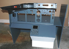
One of the things that ticks me off about the Engravity website is that the photo for the desktop MIP shows the dust shield and trigger guard on the gear lever. You can see what I'm talking about here. The photo may be from the performance panel line because it doesn't come with the desktop version. So we must make our own. Here's the (whoops - mainly out of focus) before shot from my build:


What a mess - you can see all of the gubbins in there - this won't do. So what to put in there? I've been looking for a material that won't scratch the powder coat off the gear lever. Settled on this, a thin fabric backed rubber mouse pad:

Just the right size (as you can see) and protects me with Microban! (whatever that is). A couple of cuts with a craft knife later and I sandwiched the mouse pad between the panel and the landing gear cover. Result? Acceptable if not perfect:

A couple of panels from Opencockpits arrived this week. They are for the light dimmers. Not bad quality, although thinner than the ones from Engravity. Also require their own, custom made backlighting. Knobs shown are from Opencockpits too. A little smaller than the Engravity ones but do have the locking screws on them - have yet to determine if they're functional:

I'll be back at it with the yoke and base this weekend - more later.
Monday, March 8, 2010
Progress on yoke and base
Played tourist in our own fair city with 2 colleagues from out of town. So there goes Saturday! It was good to get out though, especially since the sun finally shone on San Francisco, during what seems to be the longest rainy season on record. Sunday made some progress, despite dog walking, bike riding and tree stump chopping (ala Shane) diversions of the day. It was though, one of those days in the workshop when nothing went smoothly. I've learned under these circumstances that when the force isn't with me, I should knock it off and do something else.
There are some photos to describe however. The first shows the 2 adjustable stops I mounted in the yoke base. They allow fine tuning of the forward and back limits on the column:


There are some photos to describe however. The first shows the 2 adjustable stops I mounted in the yoke base. They allow fine tuning of the forward and back limits on the column:

Next we have more destruction on the CH products yoke. The plan was to shorten the rod that connects the handle to the gubbins inside. Before doing that, I needed to snip the wires that feed through the small hole on the rod and go to a connector. Since there are some wires which are the same color (they may be common connected and seem to go to the same lug on the connector, will figure that out later), I marked them with a Sharpie before cutting:


The rod is 1 inch in diameter. So the trick now is to bit a bung into the electrical conduit housing that reduces from 2 inch to 1 inch. As mentioned previously, my shop is more geared up for woodworking. I dug out a scrap of oak which I loosley fashioned with a jig saw to get a size that works (although I'll admit isn't a better example of my craftsmanship...). It will be hidden by the yoke so I'm not that upset by it. From here I marked the center and dropped in a 1 inch hole with my drill press:

You can see one of the screw holes in the side. Once I get the rod mounted tight to the back of the wooden bung, I'll push it back it place, align the witness marks and screw it in place so it doesn't rotate or pull out - unlikely since it's a snug fit...not that the visible gap there is any indication. Again, I can hear my shop teacher Mr. Clack yelling at me, "Son! There's enough room for a family of rats to move into that gap!". Except back in the day, what he said was a lot less politically correct...
While I had the bit in the drill press, I drilled a matching hole in the rear removable cover and cut the rod down to size so it just fits through. Why? Well the plan is to put the yoke under tension so that it returns to a neutral position in the roll axis (I'll probably use the original springs from the CH Products yoke). The rear support will provide the needed stability:

With the cover off you can see the new hole I drilled in the rod to feed the cable from the switches etc:

Can you believe that I woke up at 1:30 on Friday morning obsessing how I was going to figure out this part of the build? I ended up getting out of bed and working on some of the components - just couldn't sleep. I hope it works - I need my rest.
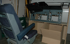
Also bolted onto the handle a real Boeing yoke clipboard (thanks Nick!), so far the only real aircraft component in the build (if you discount the seat which is still sitting in my basement). The result so far looks like this:

One thing I noticed - the heft previously reported is greatly diminshed with the extra weight at the top of the column - the 100n gas struts feel a bit weak. I'll give it a try but may up the ante and put in something stronger down the line. The more observant of you will notice some framing in the background there. It's the start of the base:

It's upside down if you were wondering. The narrow end is where the MIP (Main Instrument Panel) will be mounted. I'll cut a hole out in the plywood for the yoke unit (once I figure out exactly where...) and will then frame around it.
So that's it for the week that was. Except to say that recently I got more active in the Mycockpit forum so if you're reading this from a link I dropped over there, welcome to my folly!
Tuesday, March 2, 2010
Cracked Yoke
Ever wonder what your CH Products Yoke looked like on the inside but were too afraid to break the warranty seal to find out? Well it looks like this:


Isn't it a thing of minimalist beauty? Not a cent has been spared on unnecessary mechanics. It's a wonder it works at all. But work it does. So my plan is to strip the innards out and mount them on the yoke assembly put together last weekend. First order of business is to strip out the elevator potentiometer (that's the one on the bottom right). If I can get it to work with the home brew yoke stick, all is good. If not, I'll get a linear pot instead.
Monday, March 1, 2010
Heavy clouds, no rain
Well despite the predictions of a weekend of rain, it didn't happen. So the plan of hiding in my man cave all weekend working on the sim, didn't pan on. Rather we celebrated a friend's 50th birthday - twice. The accompanying hangovers didn't improve productivity.
Nor did another friend's question at the second party, what exciting thing did I plan to do for my 50th (also this year)? I was stumped. I wanted to say that I'll be treating myself to a Revolution Simproducts motorized throttle quadrant quickly realizing that to most outsiders, there would be nothing exciting about it at all. It really put a damper on the evening! I was struck with just what a boring tick I have become! I couldn't think of a single thing I wanted to do that would fit the general mould of "exciting" or life affirming. Race car driving? Done that. Hang gliding? Wife won't let me. Skydive? Possibly. Bungee jumping? Wouldn't mind the initial fall but not the bouncing up and down part.....
By Sunday morning I had figured it out. Will either take a real flying lesson in a real airplane (shock!) or a ride in this airship.
Back to work. I bought all the 2 X 4s and plywood for the base of the sim. Before constructing it, I decided to get the yoke mechanism working first. The plan is to mount it under the floor. I figured if I knew the exact dimensions of the yoke mechanism, I could build the rest of the base around it. My starting "plan" is a variation of the one Ian Sissons has posted. I liked his use of gas struts to give the yoke some feel and heft and found a pair from a woodwork supply store. Designed to keep cabinet doors open, they have the 100n oomph that Ian settled for in his 3rd generation design.
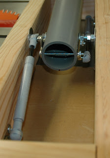
As for the upright, I'm using 2 inch electrical conduit. I'm guessing it has more strength than the drainpipe Ian used, as a consequence I can bolt components directly onto the pipe. Here it is:

The top piece is 90 degree "inspection" wire pull. It doesn't look pretty but affords a place for electronics/mechanics:


Nor did another friend's question at the second party, what exciting thing did I plan to do for my 50th (also this year)? I was stumped. I wanted to say that I'll be treating myself to a Revolution Simproducts motorized throttle quadrant quickly realizing that to most outsiders, there would be nothing exciting about it at all. It really put a damper on the evening! I was struck with just what a boring tick I have become! I couldn't think of a single thing I wanted to do that would fit the general mould of "exciting" or life affirming. Race car driving? Done that. Hang gliding? Wife won't let me. Skydive? Possibly. Bungee jumping? Wouldn't mind the initial fall but not the bouncing up and down part.....
By Sunday morning I had figured it out. Will either take a real flying lesson in a real airplane (shock!) or a ride in this airship.
Back to work. I bought all the 2 X 4s and plywood for the base of the sim. Before constructing it, I decided to get the yoke mechanism working first. The plan is to mount it under the floor. I figured if I knew the exact dimensions of the yoke mechanism, I could build the rest of the base around it. My starting "plan" is a variation of the one Ian Sissons has posted. I liked his use of gas struts to give the yoke some feel and heft and found a pair from a woodwork supply store. Designed to keep cabinet doors open, they have the 100n oomph that Ian settled for in his 3rd generation design.
As for the upright, I'm using 2 inch electrical conduit. I'm guessing it has more strength than the drainpipe Ian used, as a consequence I can bolt components directly onto the pipe. Here it is:


The upright pivots on a bolt fulcrum. The gas struts offer the necessary resistance. They are bolted through the pipe, just below the fulcrum:

Here's a top down view showing the yoke column in the neutral position:

Now the neutral position is not 90 degrees, more like 82. In an attempt to get the rig to settle at this point, I moved the forward strut closer to center:

So that's it on the mechanical side. I must say it operates very smoothly and has a pleasing pressure to the way it operates - no idea how close it comes to the real thing but much more heft required than with the CH Products yoke. A lot smoother too.
Next up, I'll put limiters in to prevent the yoke from going all forward or all back (to prevent what you see in the above photo...), put a base on it and attach the electronics. It's finally time to pull apart Bret's yoke.
Subscribe to:
Comments (Atom)


