There are some photos to describe however. The first shows the 2 adjustable stops I mounted in the yoke base. They allow fine tuning of the forward and back limits on the column:

Next we have more destruction on the CH products yoke. The plan was to shorten the rod that connects the handle to the gubbins inside. Before doing that, I needed to snip the wires that feed through the small hole on the rod and go to a connector. Since there are some wires which are the same color (they may be common connected and seem to go to the same lug on the connector, will figure that out later), I marked them with a Sharpie before cutting:


The rod is 1 inch in diameter. So the trick now is to bit a bung into the electrical conduit housing that reduces from 2 inch to 1 inch. As mentioned previously, my shop is more geared up for woodworking. I dug out a scrap of oak which I loosley fashioned with a jig saw to get a size that works (although I'll admit isn't a better example of my craftsmanship...). It will be hidden by the yoke so I'm not that upset by it. From here I marked the center and dropped in a 1 inch hole with my drill press:

You can see one of the screw holes in the side. Once I get the rod mounted tight to the back of the wooden bung, I'll push it back it place, align the witness marks and screw it in place so it doesn't rotate or pull out - unlikely since it's a snug fit...not that the visible gap there is any indication. Again, I can hear my shop teacher Mr. Clack yelling at me, "Son! There's enough room for a family of rats to move into that gap!". Except back in the day, what he said was a lot less politically correct...
While I had the bit in the drill press, I drilled a matching hole in the rear removable cover and cut the rod down to size so it just fits through. Why? Well the plan is to put the yoke under tension so that it returns to a neutral position in the roll axis (I'll probably use the original springs from the CH Products yoke). The rear support will provide the needed stability:

With the cover off you can see the new hole I drilled in the rod to feed the cable from the switches etc:

Can you believe that I woke up at 1:30 on Friday morning obsessing how I was going to figure out this part of the build? I ended up getting out of bed and working on some of the components - just couldn't sleep. I hope it works - I need my rest.
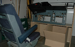
Also bolted onto the handle a real Boeing yoke clipboard (thanks Nick!), so far the only real aircraft component in the build (if you discount the seat which is still sitting in my basement). The result so far looks like this:

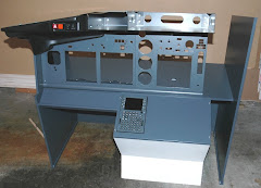
One thing I noticed - the heft previously reported is greatly diminshed with the extra weight at the top of the column - the 100n gas struts feel a bit weak. I'll give it a try but may up the ante and put in something stronger down the line. The more observant of you will notice some framing in the background there. It's the start of the base:

It's upside down if you were wondering. The narrow end is where the MIP (Main Instrument Panel) will be mounted. I'll cut a hole out in the plywood for the yoke unit (once I figure out exactly where...) and will then frame around it.
So that's it for the week that was. Except to say that recently I got more active in the Mycockpit forum so if you're reading this from a link I dropped over there, welcome to my folly!


No comments:
Post a Comment