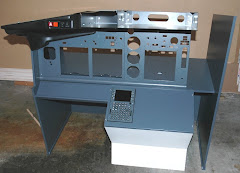
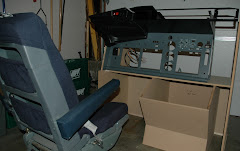
As previously reported, I have most of the parts for the first officer MIP. This means redesigning the cabinet to house everything, along with the base the captain's side is currently sitting on. Before cracking on with that, I should probably focus my attention on the control column mechanism, since it will determine the height of the base. Hence the post title - lets start with the floorboards and move up from there (cue Paul Weller...).
While I'm at it, it's really time to consider how am I ever going to move this thing when finished? The new design will be more modular and will be easier to bolt together and tear down for maintenance. But first, the control column set up.
I've taken Ivar Hestnes' design as a starting point. You'll find it here. It's really quite ingenious. Especially the use of gas struts. I've failed miserably to find a strut which in its neutral position is neither compressed or expanded. My hope was to find something that would return to neutral after being pushed or pulled. Ivar gets around this by mounting regular gas struts in aluminium tubing. Very clever but I don't have access to welding equipment. And I'm too cheap to have someone weld it for me.
Which got me thinking, since even Ivar says his welded steel frame design is overkill, what if I made mine out of bolt together angle iron instead? It's cheap enough that if it doesn't work out, I can always use it as a prototype for the finished thing. Much easier to bolt and unbolt things than to weld and un-weld.
Armed with nothing more than the following tools on hand, I got to work using Ivar's dimensions:
- A cut off saw:

- 4" grinder

- A Swanson speed square

- A hacksaw (surely you don't need a photo of one of these...)
Now before I show you the work in progress result, a quick reminder about safety with power tools if you intend to have a go yourself. Wear the appropriate safety gear and know what you're doing. When using the cut off saw and grinder, there are sparks flying everywhere. I was about to set to with just my glasses on when the wife stopped me in my tracks. Out came the full protective goggles to go over my specs.
And here is where we are so far:

Standing up on its end is one of the 2 control columns (3" pipe). It stands on the (soon to be) pivoting structure made with 2 bits of 2" angle iron bolted together. The pivot arms are made of more of the same. The rest of the frame is made out of 1 1/2" angle iron. In the foreground are 2 bits of 2" angle iron that will support the "gas" struts (more on this in a minute). Here you can see the beauty of working with angle iron - the brace on the right as been moved further to the right to "dry fit" the positioning of the strut (the left has yet to be moved). All easily done with the turn of a wrench.
Some tips if you try this yourself:
- Cut matching pieces at the same time with the bolt holes lined up together. This will result in a more square structure
- Assemble everything on a flat surface
- Use a speed square (or something similar) to make sure all of your angles are at 90 degrees
- Use bolts that are smaller that the cut outs in the angle iron. I used 1/4" bolts, the holes are 3/8". This allows you to fine tune the position of everything to ensure an accurate fit
- Use locking washers to hold everything together tight
- Make some simple braces to add to the rigidity of the frame (see left and right on the central spar)
Not shown in the photo, I also purchased some 1 1/4" square tubing to handle the torsional forces of the main pivot point. This will simply be bolted to the frame.
More close up shots for you:


Now I know this all looks a bit vague right now. It will come together in the coming weeks and I'll share progress with you.
Back to the "gas struts" and the main gubbins of this construct. I found another cunning design from Aerosim Solutions in Australia. He uses screen door closers to pull the control columns back to neutral. To get around the fact they only operate in one direction, they have come up with a slotted disk that allows the opposing closer to "disengage" when the rotation is in the other direction. Check out this video and you'll see what I mean (skip to 3:30 if you don't want to watch the whole thing):
Much easier for to fabricate a slotted disk than welding aluminum tubing.
As for the main pivot point, Ivar uses 2 x 1/4" steel plates! Way too much methinks. To prototype I simply cut a couple of pieces of 1/2" inch plywood, screwed them together and drilled all the holes the way Ivar had them. I may change this design to facilitate the Aerosim slotted plate design, here's what it looks like set on top of the frame with one of the 2 screen door closers:

The screen door closers are a great and inexpensive idea. I bought 2 heavy duty units from Home Depot at $10 a pop. The great thing about them is that they have an adjusting screw on them to control the rate of pull. Will they have enough pull to bring the columns back to neutral? That's the next step to discover. Stay tuned - flange bearings are on order from Amazon.
To close, the frame is lightweight - one person can easily pick it up, it's cheap, requires minimal metal working skills, allows for experimenting with placement etc. and appears to have enough strength to handle the loads we'll place on it.