The problems with this approach are thus:
- The springs you see there are to return the yoke to a neutral position. They pull down on the large pulley wheel making the tension adjustment on the drive belt a pain
- The original idea was to use a smaller pulley wheel attached to the potentiometer. This would put stress on it due to the belt tension and would also result in the potentiometer "pegging out" prematurely at each end of travel
My extensive search for something similar lead me to a local hobby store where I picked up a small bag of gears etc. You can order it online here if you run into the same problems I did in finding something as rudimentary as a pair of matched gears!
Back at the workshop, I filled both sides of one of the large gears with epoxy. Why? Because I'll need to drill out a 1" hole for the spindle of the yoke to fit through. I then machined out the top to make sure the gear wouldn't turn when fitted it to the spindle.
You'll notice I made an index mark on the gear wheel - more on this later. Next, I wanted to address a couple of issues in one go. In the original design, the back plate of the repurposed conduit box had a hole drilled through it to support the back of the spindle. This is fine but in addition I wanted something inside the box that would keep the spindle straight and would form the basis of a platform for the potentiometer. I turned to a piece of half inch thick polyethylene since it's easy to machine and is sturdy enough to provide support to the spindle.
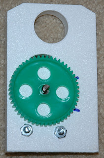
In this photo you can see I drilled a 1 inch center hole to receive the spindle and also routed out about half the depth to one side to accept the potentiometer mounting board that I salvaged from the old CH Products yoke:
You'll also see that I've machined a small "window" so I can see the gear wheel position on the backside of the board. This next photo shows the reverse view:
Notice the 2 marks. They denote the travel limit of the potentiometer. When the yoke is in the neutral position, we want the potentiometer to also be between the two limits. I marked the gear teeth on the opposite (window facing) side so I can tell where to line up this gear with the one attached to the yoke spindle. What isn't shown here is a dollop of hot glue I stuck on the potentiometer shaft to ensure a solid bond with the gear wheel.
Next a dry fit of the parts:
In the little window cut out I can see that the gears are aligned and that the potentiometer is roughly at the midway point:
I then screwed the board in place from the outside of the conduit box.
Now the tricky part of pulling the springs down and hooking them onto the retaining bolt. Fortunately I have this little gizmo, used for installing the springs on recessed light fixtures:
This next view is looking up from where the control column will attach to the yoke assembly. You can see the gears in place, the springs on the retaining bolt and the control wire from the yoke switches :
And here it is, the (almost) finished article:
Well I never said it would look pretty... It's working, really smoothly too. So pleased I scrapped the first design and started over. Next I'll work on a redo of the column base, will get the pitch potentiometer sorted out and will get this thing plugged in for a test flight soon.
Other news to report - the snows in Paris have melted and the Fedex truck was able to make it to Revolution Simproducts factory. The replacement rudder pedal panels are on route. No word yet on when we'll get my TQ sorted out but hey - it's early in the year.


Hi,
ReplyDeleteI was planning to do that in the same manner. And I got some idea of your work. Easy and cheap.
Well done.
Thanks for your comment and for listing this blog in yours. I'm really happy with the performance of the yoke, even if it does not look like the real thing. With the money saved I've been able to buy parts that I would have no chance of making so it's all good. In Amsterdam this week and was able to pick up more parts at the Aviation Megastore. Will post my "finds" when I get home.
ReplyDeleteRegards,
FlyWJP