Sunday, February 20, 2011

I got the bends

We Anoraks will sweat the smallest of details. For about a week now I've been pondering how to make the metal trim that fits around the pedestal. As previously reported, my workshop is set up for woodworking, not metal working. In terms of fashioning metals, I have limited experience (I once made a coat hook in Mr. Clack's metalworking class when I was 12...) and few of the right tools. I spent some time in the evenings last week figuring out how to go about it and running through some spare material to test my ideas.

My goal is to make the trim out of one piece of 2 inch aluminum bar, 1/8 inch thick with 2 X 90 degree bends and some fancy cut work. Since I could only find an eight foot length, I had some spare to waste in experiments. My aim here is to make 2 perfect 90 degree angles with no distortion to the bar. In other words, all sides have to be straight and flat after putting the bends in.

First test was to put a piece in the small bench vice I have, then bend it manually. The result wasn't that impressive:

The radius is too much and the side that wasn't in the vice has lost its straightness. To reduce the radius, I knew I'd need to remove some material. At this point, if he's reading this I'd advise my mate Nick (a master craftsman) to skip down to the end - he'll be horrified to see what I'm about to share with you...

My tool of choice to remove the material is a router with a carbide bit. The aluminum is a softer metal, the carbide should be able to cut through it ok. What I didn't want to do was make a deep cut in one go. To facilitate multiple shallow cuts, I built a simple jig. It's a bit of scrap wood where I've dadoed out a grove that is the exact width and depth of the aluminum bar, as shown here with the bar in place:

Running perpendicular to the wood, I've screwed in a couple of scrap bits of plastic, to act as a guide for the router:
Making a number of shallow cuts, I cut through about three quarters of the stock. When finished I simply bent the bar in 2 by hand. Result, a perfect 90 degree angle that lasted for all of 10 seconds. I flexed the thing back a little (since I'd gone further than 90 degrees) and it fell apart in my hands:

I'd cut too much out. A second attempt using a shallower cut (about half way down) and bending it in the vice resulted in a more sturdy, perfect 90 degree angle.

Saturday arrived and it was pouring down with rain. Great I thought, a full uninterrupted day in the workshop! "Not so fast" spoke the missus. It's time for that other great indoor sport that Americans enjoy at this time of year, yes you guessed it, prepare the tax return... Well if nothing else it gave me the incentive to get it done and out the way, since the next thing I was obsessing about was how to make the narrowed end of the trim.

The trim is a full 2 inches at the rear but at the front it goes down to 1 inch for about 7 inches in length. I want the thinner end to be as parallel as the thicker. My cutting tool options are limited. I opted for a jigsaw with a metal cutting blade. To stop the aluminum bar from flapping around, I screwed it down onto a scrap piece of 3/4 inch plywood. To make a parallel cut, I screwed in a fence guide for the jigsaw to push up against:

I then clamped the ensemble to the end of my workbench. Here's a shot with the jigsaw in action:

Result, a perfect straight line.

As for the angled cut, I just eyeballed it and cut it freehand:

Not bad eh? Repeated the operation on the other end. I purposely left the 2 ends a little longer than needed - I will cut them down later to get the exact dimension.

Back to the cabinet, I cut a dado all the way around the top to accommodate the metal trim. My goal is to have the trim run flush with the sides of the cabinet. Here's what it looks like:

A dry fit with the bar shows the challenge ahead - how to get the 2 X 90 degree bends in and still keep the whole thing flush to the sides:

I marked where the first bend was going in and made the cuts with the router:
Ok Nick, you can start reading again...

Now to make the first bend. I wrapped the jaws of the vice with thick pipe tape to prevent the surface of the aluminum bar from being marred. I then placed the bar in the vice vertically and clamped a piece of scrap to the end of the bar I will be bending. The pre-bend ensemble looks like this:


Here's what it looked like after pulling down on the wood/bar combo - not bad at all:
I put it back on the cabinet for another dry fit. Looking good. I made the mark for the second bend and started worrying. What if my mark is off by a fraction? Metal is a lot more unforgiving than wood. If I cuff up the second bend, it's back to the hardware store and start all over again on the fabrication. To hell with it - second bend went as smooth as the first.

Result? It fit perfectly! Oh you can believe there was some celebration tonight - rarlely does anything come together so well but my goodness it did. Next, I used a 220 grit fine sander to work out all of the saw cut marks and rounded off the cut edges. Screwed it in place and chopped off the over cuts. How does it look? Like this:
Ready for a little more filling, primer and paint. Now though, sleep. A sleep where I won't be waking up through the night panicking about those bends....

Monday, February 14, 2011

Back pedalling on the pedestal

This weekend I finally got to chat real time with a fellow sim builder (and blog follower), Gianluca. A great opportunity to compare notes (although I was doing most of the asking) and to swap ideas on design. Since his and my build are so similar in approach, we have a lot in common. In the conversation Gianluca offered up his opinion that I must be a perfectionist. I never thought so but then....

Spent any free time I had yesterday redoing the rails on the pedestal. I wasn't happy with the way the holes were lining up (see last post). Drilling bigger holes in the CPflight modules wouldn't have worked since the fake DZUS have very little wiggle room (almost none) in the face plates. My approach was to remove the rails and replace with fresh ones, mask off the units, place each on the rails in turn, drill through the face plates, tap and secure each one before moving onto the next. Given how fragile the paint is, I used a masking tape designed for such, so when you pull it off, it doesn't take the paint with it.
Then to the drill press where I very carefully drilled each hole, through the face plate of each unit. I drilled very slowly to minimize the swarf. Sometimes it can stuck on the drill bit and with it lashing around, it can strip off paint in an instant. Vigilance was key, as was the shop vac on standby to vacuum up any debris.

My plan was to shove the front units up against the MDF, get those seated then push the others up right behind. I quickly discovered though that the units still were not properly aligned! What is going on? Quick check with a set square revealed that the cabinet sides are not an accurate 90 degrees from the ends. Wouldn't normally be a big deal but with the tight tolerances of the metal work, you can see any misalignment. I wasn't about to rebuild the whole thing so I compromised with the next row of units. I set them at 90 degrees to the sides and left a small gap between them and the first row. I guess I'm not that much of a perfectionist..

Here's the finished result:

Good enough for me. Much better than it was. Although the sharp eyed of you will notice a little missing paint on the ADF. Even with masking tape for delicate jobs - beware.

I've received a couple of kind comments about the pedestal. I should acknowledge Rudy's design work, I took the idea and dimensions from here.

I should also acknowledge the comment from Rhydian about the qualities of MDF and that it can be dangerous to work with. According to this site the biggest threats are the formaldehyde leakage and the fine dust. I always wear a quality dust mask when working with the stuff and seal the finished article inside and out with primer as a minimum. Suggest you do likewise.

All for now. Will work on the metal trim and paint this week - honest I will.

Monday, January 24, 2011

Pedestal Progress

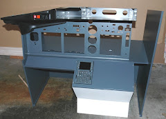
Some pics of the pedestal build out for you. Here it is during a dry fit with the TQ etc:
The ah, Captain's chair you see there is temporary - trust me. The case is made of MDF (Medium Density Fiberboard), devil to work with but sands really smooth and is stable. The units are sitting on aluminum angle brackets that are screwed and epoxy glued into the side and on the 2 center supports. I covered the rails with masking tape, set the units down on top and marked where the holes should be drilled:

And here's where you see my cock up. My brainwave was to cut 2 dados in the back and front to slide the center supports into. The idea being that this would ensure they would be perfectly parallel to each other and that I could easily adjust the height of the supports to have all rails be nice and level. As you can see, I put the dados in on the wrong side of the mark I made. Doh! Hence the added strip of MDF nailed to the top of the sliders. Once it's covered up you'll never see it, I was cross with myself anyway and too lazy to redo the end pieces.

You'll also notice the bit of metal I have on the back, where the fire handles go and the whole thing backs up to the TQ. It's from an old laserdisc player that had seen better days. It also has this cool sticker on the back which I of course saved (what an anorak!):


I made a small rabbet to keep the whole thing flush. Another construction photo for you that simply shows how the sides of the case are nailed to support members inside:

All the nail holes and small gaps have been filled with Bondo. Now a word about drilling the holes for the mounting screws. Even with a hefty drill press and being as accurate as I could be, the tolerances on these units from CPFlight are very tight. The supplied bolts are about the same size as the holes in the units themselves. In my final dry fit before painting, I can see that the drilled and tapped holes in the aluminum strip don't always quite match up with the holes in the units, like this:
The solution is for me to drill bigger holes in the some of the CPFlight units, not something I'm thrilled about of course. Note to CPFlight, make the holes bigger so we don't have to.

Wife heads out today for a 10 day business trip in Europe - I'll be putting more hours in on the sim. Next up, paint the pedestal and get the base finished.

Tuesday, January 18, 2011

Revolution Simproducts TQ: Progress - slowly but surely

Having re-installed FSX and the Accelerator add on, I spent some time yesterday checking out the Revolution Simproducts TQ. It's coming together. After calibrating the TQ one more time and running the PMDG TQ software from RS (instead of the Project Magenta one - apparently it needs more work), I was able to get the thrust lever moving. Especially rewarding when you press the N1 button and you see the levers move forward and the engines spool up. Also a joy to be hauling away on a proper flaps lever and not pressing F7 or F6 on a keyboard...

Levers are working, as is the spoiler and engine cutoff switches. Still to get working are the TOGA buttons, reverse thrusters, AT disconnect and spoiler deployment on landing. I await further instructions.

Also last night hooked up all of the CP Flight radio units etc. MIP board and the fire handles. They are looking superb although I'm struggling to get the power connection to the MIP board working. Instead I'm forced to run power through the MCP, however I understand with so many units daisy chained, you're better off with power on the board. Will keep you informed on this one too.

Off on a brief business trip tomorrow - can't wait to get home to finish off the pedestal.

Sunday, January 16, 2011

Mini weekend post

Started Saturday bright and early on a call with Eren from Revolution Simproducts and Ian Sissons. I really appreciate the time they spent with me to get the TQ going. We ran some tests and concluded that the hardware is all working fine and that the problem is software related. Not least of which, when I set up my banging new computer for FSX, I forgot to apply SP1 and SP2. Whoops... I de-installed everything and I'm in the process of putting it all back together, to ensure I have a clean install.

For a good part of the weekend I worked on the pedestal cabinet. Sorry, no photos just yet. It all went together beautifully except for one miscalculation on the clearance I needed for the middle 2 mounting rails. Once I figure it out I'll post some in progress photos. Then it's time to fill the nail holes, sand, prime and paint. May be able to complete during the week.

Monday, January 10, 2011

Yoke finished

I'll resist "cracking" another dumb joke like the "yolk" is on me..

The yoke is finished and awaits mounting in the new base. More construction notes for you. First off, I added a couple of terminal blocks inside the yoke for the roll potentiometer and the other switches on the yoke handle:
 
In the base I needed to beef up the stops I had in there to limit the travel of the column to 10 degrees forward and back. I used some cut down blocks of 2X4 that are long enough to push up against the ends of the base. More on that in a moment. What I want to show in the next photo is the mounting plate for the elevator potentiometer. I re-used the mount from the CH Products yoke, since I can use the trim tab to fine tune the calibration of the potentiometer. It's the little lever you see in the photo. With this you can adjust the offset of the potentiometer, important since it's range of usefulness is quite narrow, more so than the pot on the roll control. I screwed the mounting plate onto a scrap of plastic, to make it easier to move it up and down the wooden stop that you see here:
Note the adjustable end stop on the wooden block. This allows fine tuning to ensure that the control column travel is within specs. Next photo shows the block in the base with the potentiometer hooked up. Note the metal rod that is connected to the column base and then to the lever on the pot:

Now we need to wire it all up to the control board. It's on the other (forward) side of the base, mounted on top of the stop block. You can also see the 2 cat 5 cables coming out of a hole drilled in the bottom of the column. There's not a lot of travel and despite the seeming mess of wires, nothing tangles up on anything.
Eagle eyes will notice a couple of switched thrown in behind the control board. These micro switches are from the old yoke base. I may have a use for them later, in the meanwhile I've just tucked them in here since they're wired up to everything else. The old throttle, mix and trim potentiometers that were also in the base were connected via a quick connect on the board. It  seems to work fine without them so I've disconnected them completley. I may have use for them in the future - we'll see.

Now to test and fine tune the calibration. When I first hooked it up the roll worked fine, as did all of the switches on the yoke. Unbelievable! As far as my computer and FSX was concerned, I'd just plugged in a CH Products yoke. What didn't seem to be working was the elevator potentiometer. This is where the calibration comes in.

You can get to the calibration a couple of ways. In these examples I launched the CH Products calibration software from within FSX:
What we're looking for is movement on the Y axis, that's the little dot in the square box on the left. If you don't see any movement (or limited movement) in this box, move the adjusting lever on the CH Products mounting plate (as shown in the 3rd photo above) until you can see the full range of travel. With the column full forward, the dot should be at the top:
Full back the dot should be at the bottom: 
Dot doesn't cover the complete distance? You'll need to adjust how far up or down the connecting rod is on the potentiometer lever.

Bottom line: this thing works and it's cheap. It also means I don't need to order any more gear from bolshy Europeans...

Talking of which, I received some new software from our good friends at Revolution Simproducts. I'm happy to report that the flaps and spoiler levers are now working. Still a bunch of other things that aren't but I'm sure that in another month or so, we'll get it all working....

Also heard from CP Flight, my new units and replacement MIP card are on the way. Hurrah!

Monday, January 3, 2011

Happy New Yoke!

Since I was away from the workshop for a week or so, I got to thinking about the yoke design. You may recall from way back when that I was putting together a contraption using pulleys and a tensioned belt, ala this:
The problems with this approach are thus:
  • The springs you see there are to return the yoke to a neutral position. They pull down on the large pulley wheel making the tension adjustment on the drive belt a pain
  • The original idea was to use a smaller pulley wheel attached to the potentiometer. This would put stress on it due to the belt tension and would also result in the potentiometer "pegging out" prematurely at each end of travel
Without tools and materials to muck around with, I got to thinking about a different approach. To remove the tension issue, I decided to go with gears instead of the pulley wheels. When I was a lad this would be an easy affair, I'd dip into my Meccano set and pull out the appropriate sized gears and be done. In this day and age, Meccano has become something you turn to if you want to build a robot, race car or inter-galactic troop carrier. In short, they don't make the gears, sprockets, chains, bars and girders like they used to.

My extensive search for something similar lead me to a local hobby store where I picked up a small bag of gears etc. You can order it online here if you run into the same problems I did in finding something as rudimentary as a pair of matched gears!

Back at the workshop, I filled both sides of one of the large gears with epoxy. Why? Because I'll need to drill out a 1" hole for the spindle of the yoke to fit through. I then machined out the top to make sure the gear wouldn't turn when fitted it to the spindle.
You'll notice I made an index mark on the gear wheel - more on this later.
Next, I wanted to address a couple of issues in one go. In the original design, the back plate of the repurposed conduit box had a hole drilled through it to support the back of the spindle. This is fine but in addition I wanted something inside the box that would keep the spindle straight and would form the basis of a platform for the potentiometer. I turned to a piece of half inch thick polyethylene since it's easy to machine and is sturdy enough to provide support to the spindle.

In this photo you can see I drilled a 1 inch center hole to receive the spindle and also routed out about half the depth to one side to accept the potentiometer mounting board that I salvaged from the old CH Products yoke:

You'll also see that I've machined a small "window" so I can see the gear wheel position on the backside of the board. This next photo shows the reverse view:

Notice the 2 marks. They denote the travel limit of the potentiometer. When the yoke is in the neutral position, we want the potentiometer to also be between the two limits. I marked the gear teeth on the opposite (window facing) side so I can tell where to line up this gear with the one attached to the yoke spindle. What isn't shown here is a dollop of hot glue I stuck on the potentiometer shaft to ensure a solid bond with the gear wheel.

Next a dry fit of the parts:

In the little window cut out I can see that the gears are aligned and that the potentiometer is roughly at the midway point:

I then screwed the board in place from the outside of the conduit box.

Now the tricky part of pulling the springs down and hooking them onto the retaining bolt. Fortunately I have this little gizmo, used for installing the springs on recessed light fixtures:

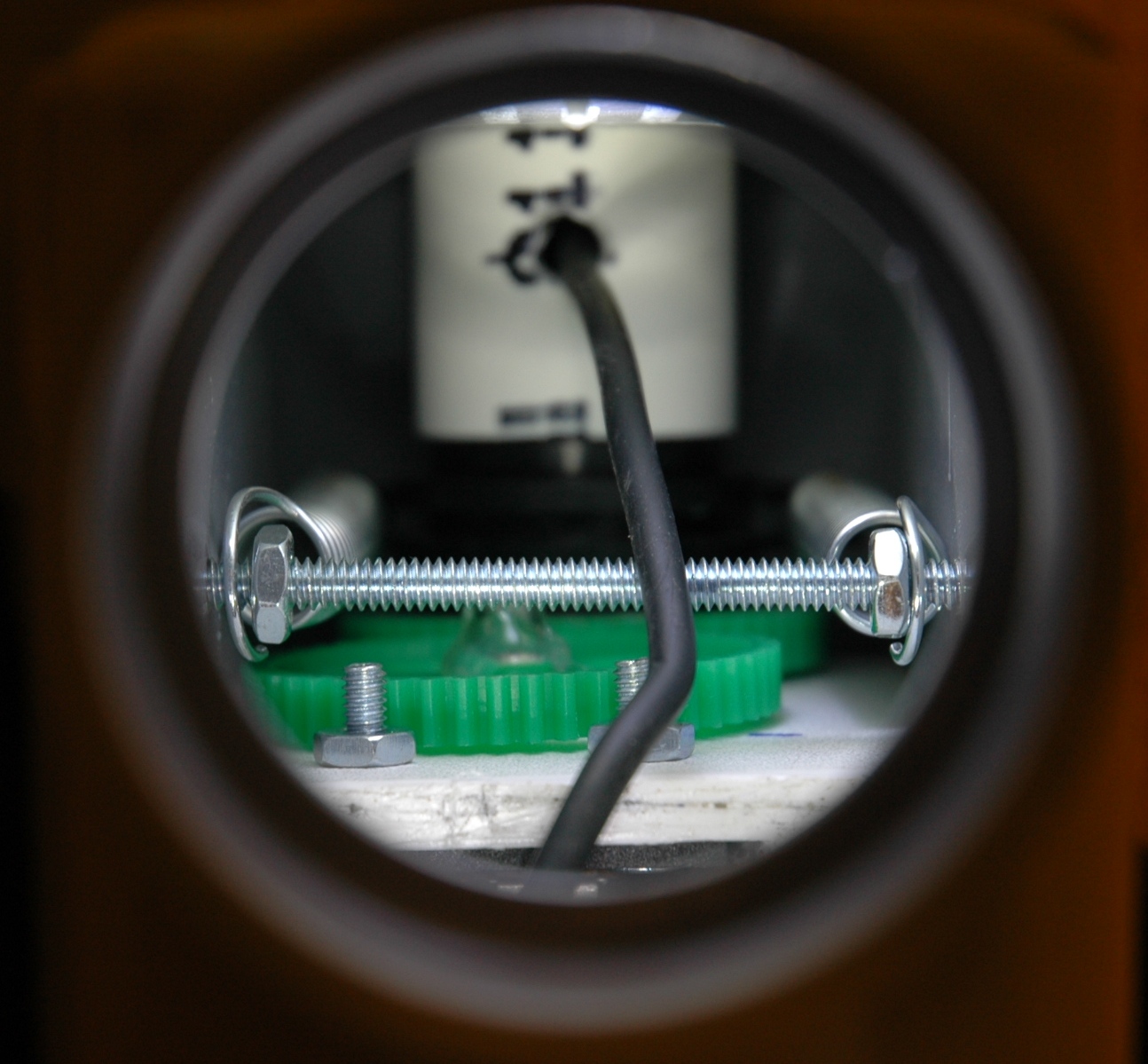
This next view is looking up from where the control column will attach to the yoke assembly. You can see the gears in place, the springs on the retaining bolt and the control wire from the yoke switches :
 And here it is, the (almost) finished article:
Well I never said it would look pretty... It's working, really smoothly too. So pleased I scrapped the first design and started over. Next I'll work on a redo of the column base, will get the pitch potentiometer sorted out and will get this thing plugged in for a test flight soon.

Other news to report - the snows in Paris have melted and the Fedex truck was able to make it to Revolution Simproducts factory. The replacement rudder pedal panels are on route. No word yet on when we'll get my TQ sorted out but hey - it's early in the year.